Challenges
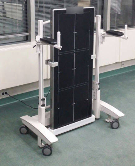
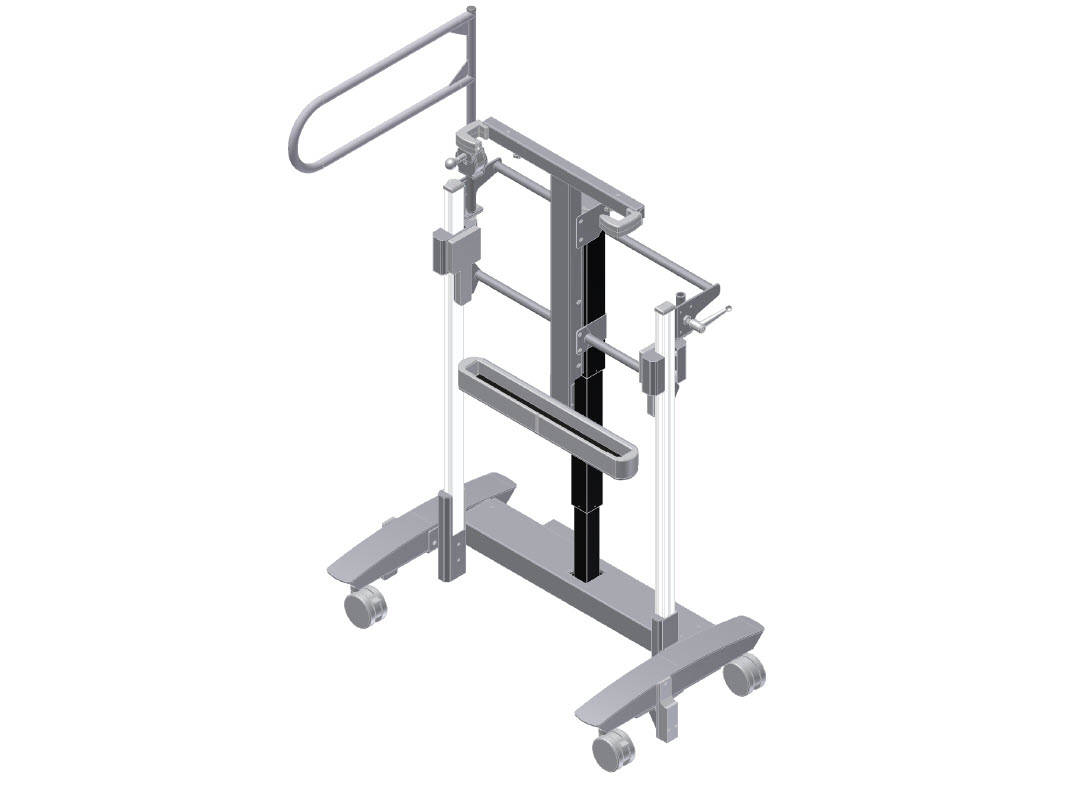
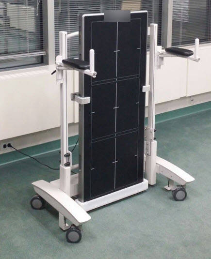
One challenge was that the detector had a large amount of the front surface for imaging. I could not block the detector with metal, and additionally, there was a grid that could be mounted in front if the client preferred. Every month or so, there was a need to calibrate the detector using what is called a phantom, so consideration was needed there too. Due to the height range requested by the client, the unit had a foot safety issue, the clearance at the floor to the lowest position of the detector would be a pinch point. Also, the unit had to hold the weight of a "lean" bar on top for patients with difficulty standing vertically. To add to this the unit had be grounded from top to bottom.
Solutions
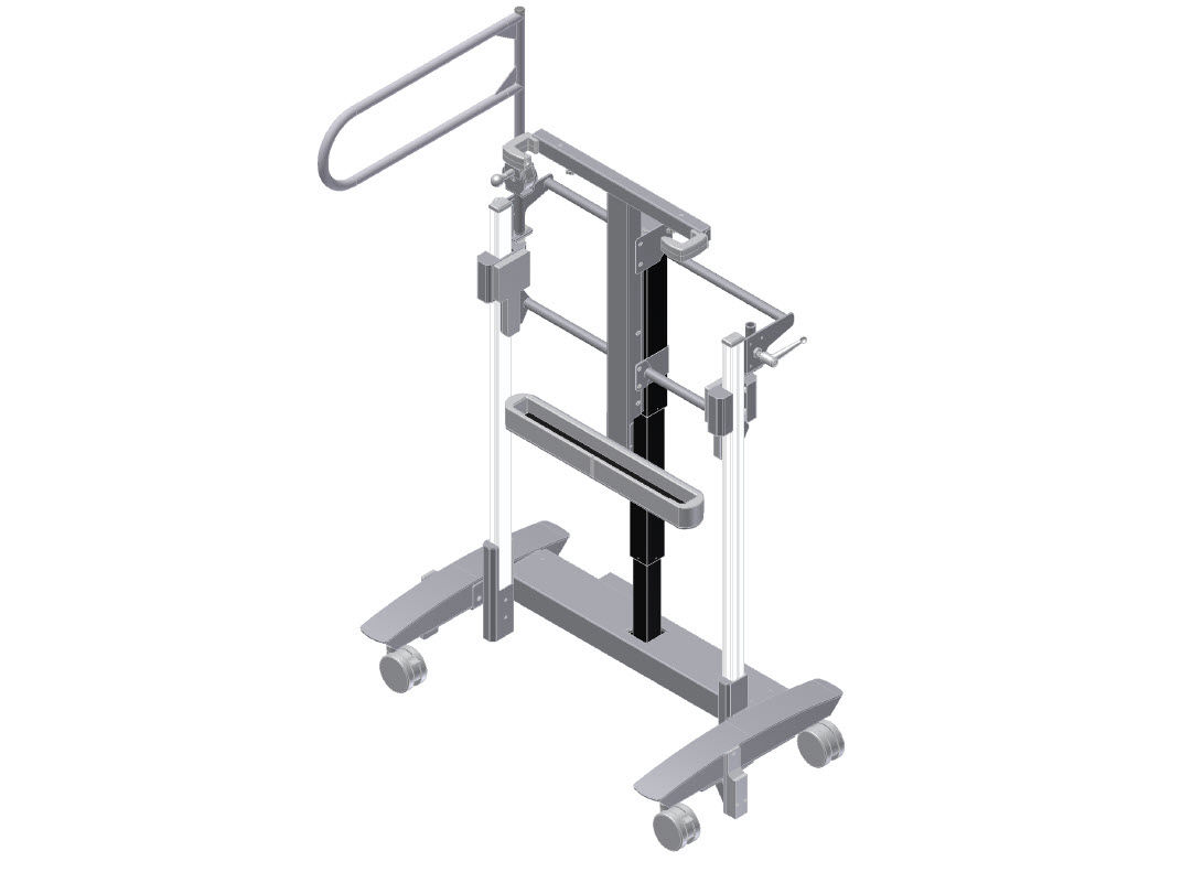
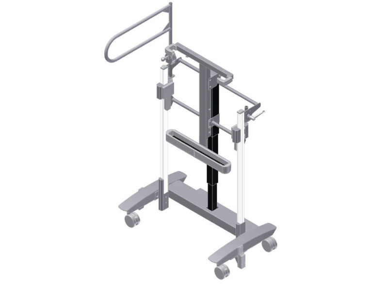
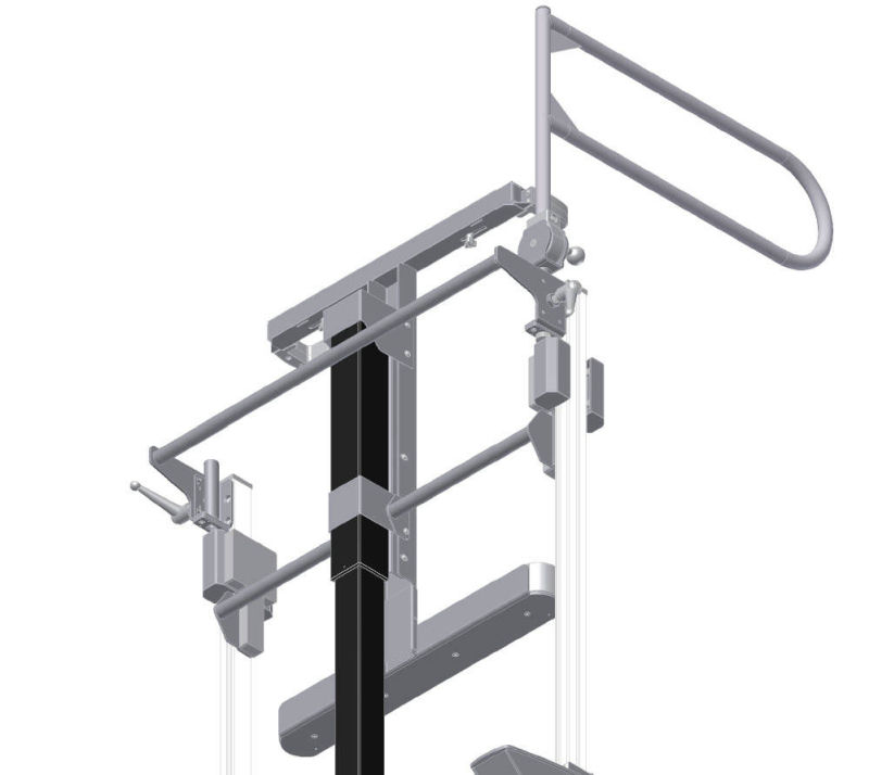
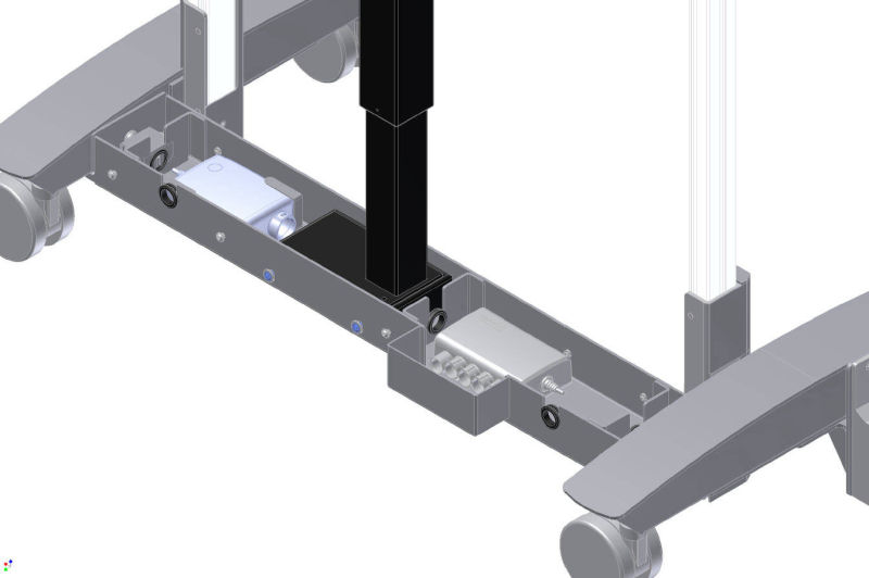
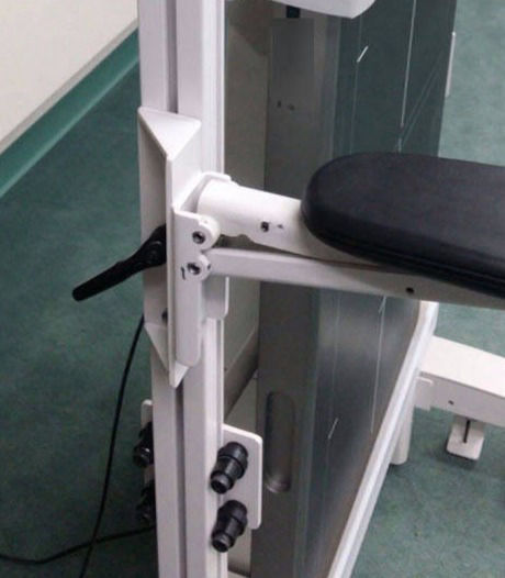
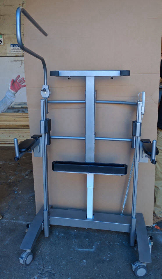
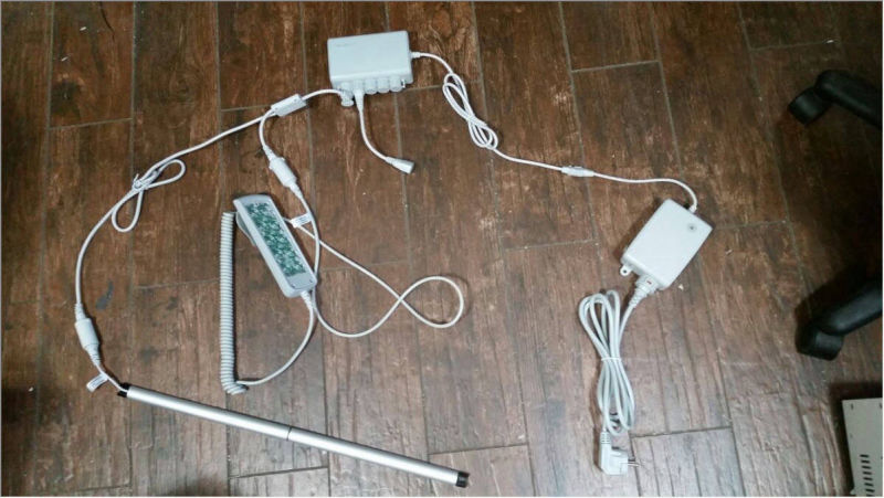
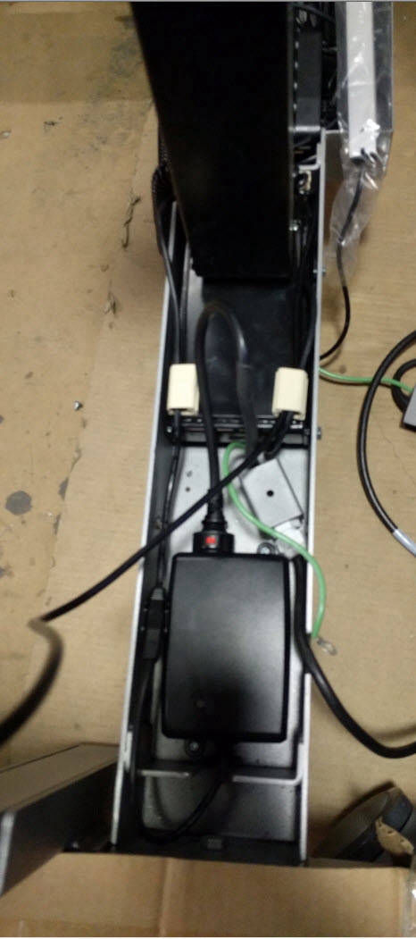
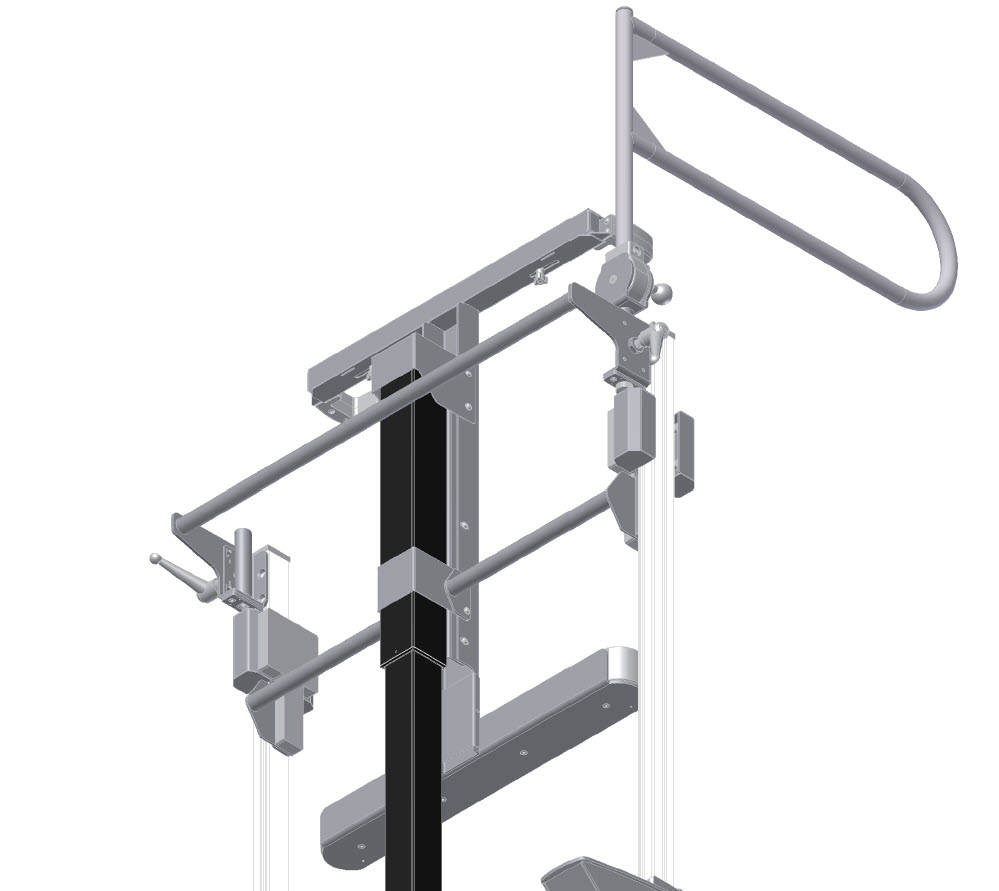
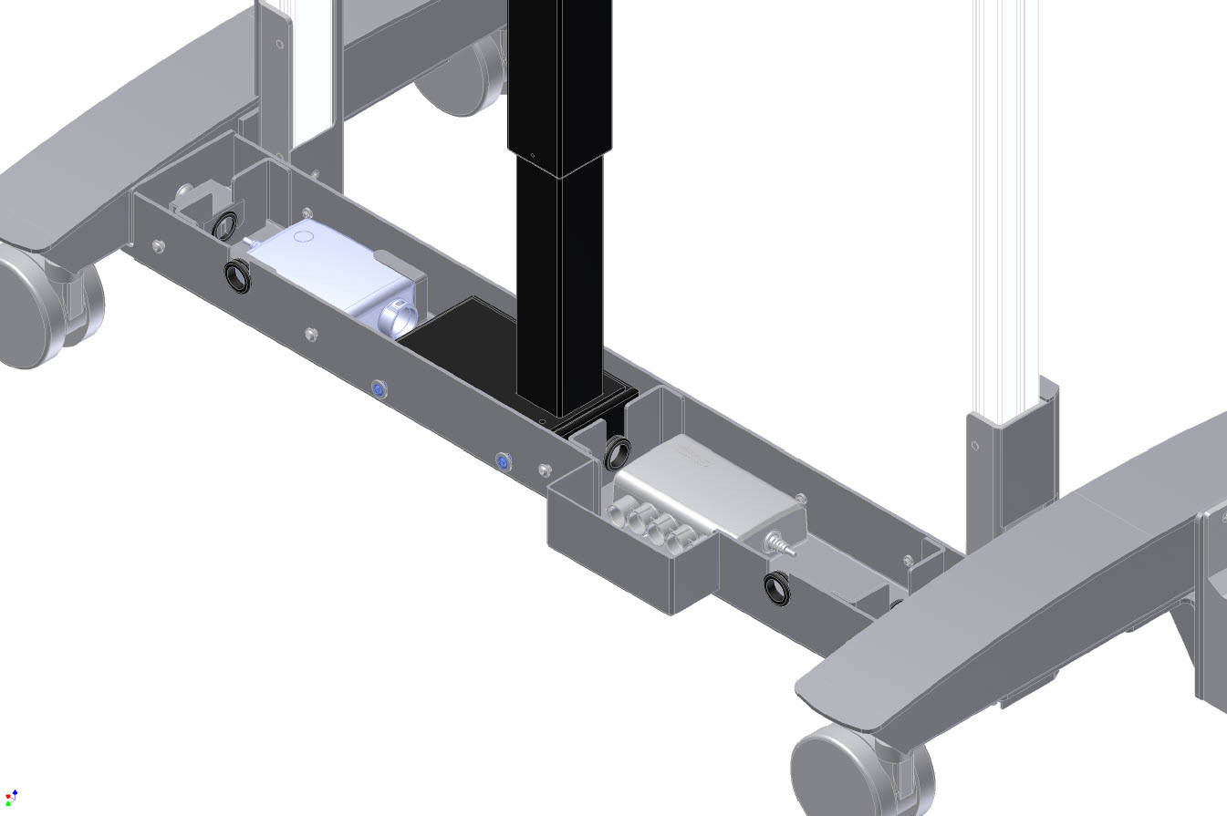
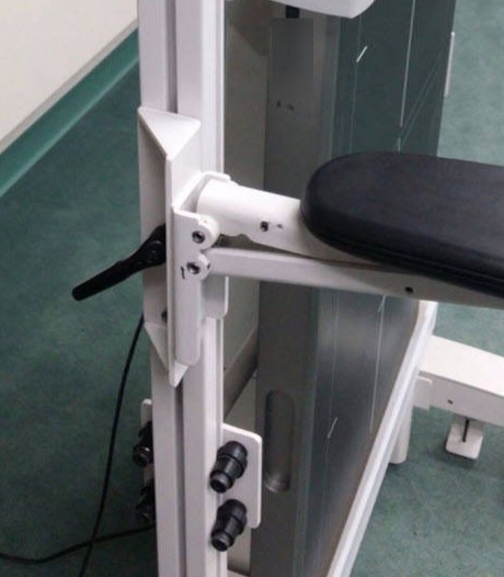
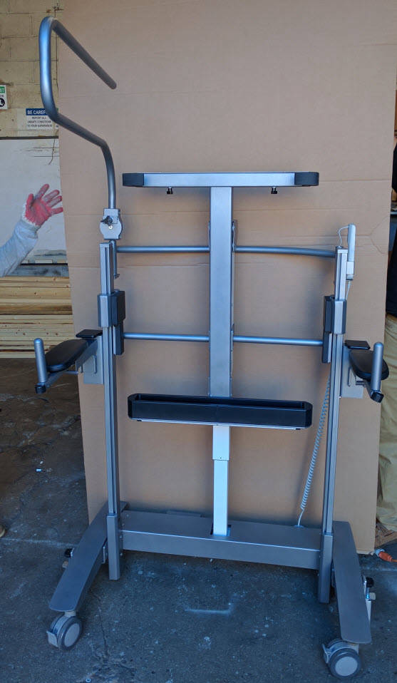
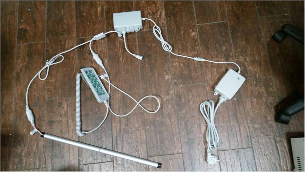
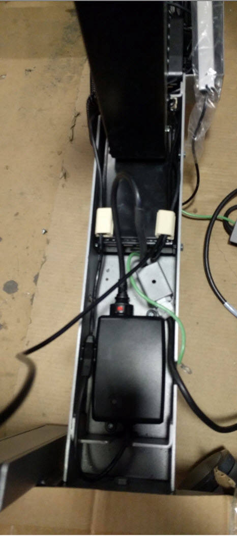
As a new design from the ground up, the unit had several hurdles; from a mechanical side, the unit was designed in such a way that the majority of the weight was distributed to the bottom. The stand was still stable when the detector was all the way up. Additional reinforcements were added to support the "lean" bar, along with a selection of an extrusion that can support that weight and act as tracks for the vertical dolly. The clamps and basket were designed to contact the detector while avoiding the detection area; they also had cutouts to seat a grid snuggle while letting a phantom holding rig in place, which would position the phantoms perfectly for each smaller detection zones on the panel. The unit had a grounding wire that linked the top area with the base hidden within the vertical center column, and all the electrical components was hidden from users except for the hand switch, which can hook onto the rear handlebar. To resolve the pinch point issue, a long contact switch was added to the bottom of the basket to break the connection if the obstruction was detected.
This project was interesting as the design for the detector holder had to be as structurally sound as possible. During design, many different track systems were considered, including ball bearing recirculating dollies and multiple linear actuators. However, the cost would have been too high for the client if used. Another interesting point of the project was the design of the safety switch; many demos were made for testing the circuit so that it would trip from the slightest touch of the human foot, as if it took too long to detect an obstruction, it would feel uncomfortable. The design went from a mechanical lever that would contact a switch when touched to a laser safety switch (typically used in heavy manufacturing machines for safety) which would activate when the laser line was broken. After some work with vendor, we were able to get a long contact switch that would activate when a soft hollow tube bends a bit.
